22 Linux SPI 驱动
这里讨论Linux kernel SPI控制器驱动, 也即使用GPIO bitbang模拟SPI功能的驱动, 类似drivers/spi/spi-rockchip.c或者spi-imx.c等SPI Controller控制器驱动。
实际上在Kernel里已经有这样的驱动, 代码在drivers/spi/spi-gpio.c。 spi-gpio.c 是 Linux 内核中使用 GPIO 模拟 SPI 控制器的驱动。它实现了一种bit-banging 的方式,通过软件直接控制 GPIO 引脚来模拟 SPI 通信协议。这种方式常用于那些没有硬件 SPI 控制器的系统,或者那些需要使用特定 GPIO 引脚而非专用 SPI 总线的场景。该驱动实现了标准的 SPI 主控制器功能,允许 SPI 设备通过 GPIO 引脚进行通信。
22.1 DTS配置
由于是使用GPIO模拟SPI host controller, 故需要先配置DTS。 如下:
demo_spi: spi@10 {
compatible = "spi-gpio";
sck-gpios = <&gpio1 RK_PA2 0>; /* SCLK */
mosi-gpios = <&gpio1 RK_PA4 0>; /* MOSI */
miso-gpios = <&gpio2 RK_PB6 0>; /* MISO */
cs-gpios = <&gpio1 RK_PB0 0>; /* CS */
pinctrl-names = "default";
pinctrl-0 = <&demo_spi_pin>;
num-chipselects = <1>;
spi-max-frequency = <1000000>; /* 1 MHz */
#address-cells = <1>; /* Define number of address cells (1 for chip select) */
#size-cells = <0>; /* Define number of size cells (0 for SPI devices) */
/* Child node for spidev */
spidev@0 {
compatible = "neardi,spidev";
reg = <0>; /* Chip Select 0 */
spi-max-frequency = <1000000>; /* Max frequency for the device */
};
};
&pinctrl {
demo_spi {
demo_spi_pin: demo_spi_pin {
rockchip,pins = <1 RK_PA2 RK_FUNC_GPIO &pcfg_pull_none>,
<1 RK_PA4 RK_FUNC_GPIO &pcfg_pull_none>,
<2 RK_PB6 RK_FUNC_GPIO &pcfg_pull_none>,
<1 RK_PB0 RK_FUNC_GPIO &pcfg_pull_none>;
function = "spi";
};
};
22.2 Kernel选项
在编译kernel时, 需要勾选如下配置:
- 启用 SPI 支持,SPI 子系统是 SPI 设备和控制器驱动工作的基础。
Device Drivers --->
<*> SPI support --->
- 勾选 GPIO 模拟 SPI 驱动 (spi-gpio.c)
Device Drivers --->
<*> SPI support --->
<*> GPIO-based bitbanging SPI master
- 启用 GPIO 支持
Device Drivers --->
[*] GPIO Support --->
<*> GPIO Generic bitbanged SPI support
- 用户空间 SPI 驱动支持 (spidev)
Device Drivers --->
<*> SPI support --->
<*> User mode SPI device driver support
22.3 SPI Bit-banging 机制
在标准的 SPI 控制器中,硬件负责生成 SPI 时钟(SCK)并管理数据线(MOSI 和 MISO)。然而,在没有硬件 SPI 控制器的情况下,bit-banging 通过软件来模拟这些信号时序,手动控制 GPIO 引脚的电平以符合 SPI 协议规范
由前2章所描述, 典型的 SPI 通信包括:
SCK(Serial Clock):时钟信号,由主设备生成,控制数据传输的时序。
MOSI(Master Out Slave In):主设备发送数据给从设备。
MISO(Master In Slave Out):从设备发送数据给主设备。
CS(Chip Select):选择从设备的信号,低电平有效。
在 bit-banging 中,软件负责根据 SPI 协议的时序控制这些信号。如下代码所示:
static u32 spi_gpio_txrx_word_mode0(struct spi_device *spi,
unsigned nsecs, u32 word, u8 bits, unsigned flags)
{
return bitbang_txrx_be_cpha0(spi, nsecs, 0, flags, word, bits);
}
static u32 spi_gpio_txrx_word_mode1(struct spi_device *spi,
unsigned nsecs, u32 word, u8 bits, unsigned flags)
{
return bitbang_txrx_be_cpha1(spi, nsecs, 0, flags, word, bits);
}
static u32 spi_gpio_txrx_word_mode2(struct spi_device *spi,
unsigned nsecs, u32 word, u8 bits, unsigned flags)
{
return bitbang_txrx_be_cpha0(spi, nsecs, 1, flags, word, bits);
}
static u32 spi_gpio_txrx_word_mode3(struct spi_device *spi,
unsigned nsecs, u32 word, u8 bits, unsigned flags)
{
return bitbang_txrx_be_cpha1(spi, nsecs, 1, flags, word, bits);
}
22.4 驱动注册流程
spi-gpio.c 通过 Linux SPI 子系统进行集成,它会注册为一个 SPI 控制器,并通过 GPIO 来模拟 SPI 时钟、数据线和芯片选择线。
22.4.1 驱动注册流程概述
分配 SPI 控制器: 驱动通过调用 devm_spi_alloc_master() 来分配一个 spi_master 结构体,该结构体表示一个 SPI 控制器。
设置 SPI 控制器属性:初始化 spi_master 的各类属性,比如 SPI 模式支持、字长范围、总线号、设备的 setup 和 cleanup 方法等。
配置 GPIO 引脚:驱动调用 spi_gpio_request() 等函数来配置 SPI 所需的 GPIO 引脚(SCK、MOSI、MISO、CS)。
设置 Bit-bang 操作:驱动将具体的 GPIO 操作函数与 spi_bitbang 结构体相关联,定义如何通过软件控制 GPIO 引脚以进行 SPI 数据传输。
初始化 Bit-bang 控制器:调用 spi_bitbang_init() 完成 bit-banging SPI 控制器的初始化。
注册 SPI 控制器:最后调用 spi_register_master() 将模拟的 SPI 控制器注册到 Linux 内核中,使其能够被 SPI 子系统使用。
22.4.2 代码解析
static int spi_gpio_probe(struct platform_device *pdev)
{
int status;
struct spi_master *master;
struct spi_gpio *spi_gpio;
struct device *dev = &pdev->dev;
struct spi_bitbang *bb;
master = devm_spi_alloc_master(dev, sizeof(*spi_gpio));
if (!master)
return -ENOMEM;
if (pdev->dev.of_node)
status = spi_gpio_probe_dt(pdev, master);
else
status = spi_gpio_probe_pdata(pdev, master);
if (status)
return status;
spi_gpio = spi_master_get_devdata(master);
status = spi_gpio_request(dev, spi_gpio);
if (status)
return status;
master->bits_per_word_mask = SPI_BPW_RANGE_MASK(1, 32);
master->mode_bits = SPI_3WIRE | SPI_3WIRE_HIZ | SPI_CPHA | SPI_CPOL |
SPI_CS_HIGH;
if (!spi_gpio->mosi) {
/* HW configuration without MOSI pin
*
* No setting SPI_MASTER_NO_RX here - if there is only
* a MOSI pin connected the host can still do RX by
* changing the direction of the line.
*/
master->flags = SPI_MASTER_NO_TX;
}
master->bus_num = pdev->id;
master->setup = spi_gpio_setup;
master->cleanup = spi_gpio_cleanup;
bb = &spi_gpio->bitbang;
bb->master = master;
/*
* There is some additional business, apart from driving the CS GPIO
* line, that we need to do on selection. This makes the local
* callback for chipselect always get called.
*/
master->flags |= SPI_MASTER_GPIO_SS;
bb->chipselect = spi_gpio_chipselect;
bb->set_line_direction = spi_gpio_set_direction;
if (master->flags & SPI_MASTER_NO_TX) {
bb->txrx_word[SPI_MODE_0] = spi_gpio_spec_txrx_word_mode0;
bb->txrx_word[SPI_MODE_1] = spi_gpio_spec_txrx_word_mode1;
bb->txrx_word[SPI_MODE_2] = spi_gpio_spec_txrx_word_mode2;
bb->txrx_word[SPI_MODE_3] = spi_gpio_spec_txrx_word_mode3;
} else {
bb->txrx_word[SPI_MODE_0] = spi_gpio_txrx_word_mode0;
bb->txrx_word[SPI_MODE_1] = spi_gpio_txrx_word_mode1;
bb->txrx_word[SPI_MODE_2] = spi_gpio_txrx_word_mode2;
bb->txrx_word[SPI_MODE_3] = spi_gpio_txrx_word_mode3;
}
bb->setup_transfer = spi_bitbang_setup_transfer;
status = spi_bitbang_init(&spi_gpio->bitbang);
if (status)
return status;
return devm_spi_register_master(&pdev->dev, master);
}
devm_spi_alloc_master():分配 SPI 控制器结构 spi_master,并关联设备。
spi_gpio_request():请求 GPIO 资源,为 SPI 控制器的时钟、数据线和片选线分配 GPIO。
spi_bitbang_init():初始化 bit-banging,配置通过 GPIO 模拟 SPI 的操作。
devm_spi_register_master():将控制器注册到 SPI 核心层,使得内核可以通过该控制器管理 SPI 设备。
22.5 数据传输与接口
在 spi-gpio 中,数据传输是通过 bit-banging 实现的,SPI 控制器的 txrx_word 系列函数用于定义如何在不同 SPI 模式下传输数据。这些函数将通过软件模拟 SPI 时钟周期,并控制数据传输方向。
static inline u32
bitbang_txrx_be_cpha0(struct spi_device *spi,
unsigned nsecs, unsigned cpol, unsigned flags,
u32 word, u8 bits)
{
/* if (cpol == 0) this is SPI_MODE_0; else this is SPI_MODE_2 */
u32 oldbit = (!(word & (1<<(bits-1)))) << 31;
/* clock starts at inactive polarity */
for (word <<= (32 - bits); likely(bits); bits--) {
/* setup MSB (to slave) on trailing edge */
if ((flags & SPI_MASTER_NO_TX) == 0) {
if ((word & (1 << 31)) != oldbit) {
setmosi(spi, word & (1 << 31));
oldbit = word & (1 << 31);
}
}
spidelay(nsecs); /* T(setup) */
setsck(spi, !cpol);
spidelay(nsecs);
/* sample MSB (from slave) on leading edge */
word <<= 1;
if ((flags & SPI_MASTER_NO_RX) == 0)
word |= getmiso(spi);
setsck(spi, cpol);
}
return word;
}
该函数通过软件控制 GPIO 引脚的电平,模拟 SPI 时钟周期,并在每个周期中发送和接收一位数据。
22.6 SPI 设备控制
当 spi-gpio 被注册为 SPI 控制器后,应用程序可以通过标准的 SPI API 与设备通信。应用层通常会打开 /dev/spidevX.Y 设备接口,并通过 read() 和 write() 函数与 SPI 设备进行数据传输。
22.6.1 用户空间与 SPI 通信流程
- 打开 SPI 设备: 用户空间应用可以通过打开 /dev/spidevX.Y 设备文件来访问 SPI 设备。
int fd = open("/dev/spidev0.0", O_RDWR);
- 配置 SPI 参数: 使用 ioctl 设置 SPI 模式、位宽、时钟速度等。
int mode = SPI_MODE_0;
ioctl(fd, SPI_IOC_WR_MODE, &mode);
- 读写数据: 使用 read() 和 write() 或 ioctl(SPI_IOC_MESSAGE) 与设备通信。
struct spi_ioc_transfer tr = {
.tx_buf = (unsigned long)tx_buffer,
.rx_buf = (unsigned long)rx_buffer,
.len = sizeof(tx_buffer),
};
ioctl(fd, SPI_IOC_MESSAGE(1), &tr);
22.7 测试驱动
22.7.1 验证GPIO配置
重新编译kernel及下载到设备, 则可以查看gpio的配置信息, 有如下:
neardi@LPA3588:~$ sudo cat /sys/kernel/debug/gpio
gpiochip1: GPIOs 32-63, parent: platform/fec20000.gpio, gpio1:
gpio-34 ( |sck ) out lo
gpio-36 ( |mosi ) out lo
gpio-40 ( |spi6 CS0 ) out hi ACTIVE LOW
gpio-41 ( |vcc-mipidphy1-regula) out lo
gpio-42 ( |vcc-mipidphy0-regula) out lo
gpio-44 ( |reset ) out hi
gpio-52 ( |hp-det ) in hi ACTIVE LOW
gpio-54 ( |work1 ) out hi ACTIVE LOW
gpio-58 ( |vcc5v0_host_pwren ) out hi
gpio-61 ( |hdmirx-det ) in hi ACTIVE LOW
gpio-62 ( |enable ) out hi
gpio-63 ( |reset ) out hi
gpiochip2: GPIOs 64-95, parent: platform/fec30000.gpio, gpio2:
gpio-78 ( |miso ) in hi
gpio-81 ( |enable ) out hi
从上面信息可以看见成功地配置了SPI GPIO。
22.7.2 检查/dev/spidevX.Y
驱动运行成功后, 会创建/dev/spidevX.Y设备, X表示SPI bus号, Y表示此bus上面的设备号。 如下:
neardi@LPA3588:~$ ls /dev/spidev6.0 -l
crw------- 1 root root 153, 0 Sep 25 15:55 /dev/spidev6.0
这里的/dev/spidev6.0中的6, 表示SPI bus 6, 是kernel动态创建的, 与注册到kernel SPI核心的顺序有关。
22.7.3 测试App
创建一个测试程序, app.cpp, 代码如下:
#include <stdio.h>
#include <stdlib.h>
#include <string.h>
#include <fcntl.h>
#include <unistd.h>
#include <sys/ioctl.h>
#include <linux/spi/spidev.h>
#define DEVICE "/dev/spidev6.0"
#define READ_ID_CMD 0x9F // JEDEC ID read command
// configurate SPI mode, clock and word length.
int configure_spi(int fd, unsigned char mode, unsigned int speed, unsigned char bits_per_word) {
if (ioctl(fd, SPI_IOC_WR_MODE, &mode) < 0) {
perror("Unable to set SPI mode");
return -1;
}
if (ioctl(fd, SPI_IOC_WR_MAX_SPEED_HZ, &speed) < 0) {
perror("Unable to set SPI speed");
return -1;
}
if (ioctl(fd, SPI_IOC_WR_BITS_PER_WORD, &bits_per_word) < 0) {
perror("Unable to set SPI bits per word");
return -1;
}
return 0;
}
// read SPI NOR Flash ID
int read_flash_id(int fd, unsigned char *rx_buf, size_t len) {
unsigned char tx_buf[1];
// constructure read ID command
tx_buf[0] = READ_ID_CMD;
struct spi_ioc_transfer tr = {
.tx_buf = (unsigned long)tx_buf,
.rx_buf = (unsigned long)rx_buf,
.len = (__u32)(len + 1), // 1 bye command
.speed_hz = 0,
.delay_usecs = 0,
.bits_per_word = 0,
.cs_change = 0
};
// send reading ID command and receive ID data
if (ioctl(fd, SPI_IOC_MESSAGE(1), &tr) < 0) {
perror("SPI transfer failed");
return -1;
}
return 0;
}
int main() {
int fd;
unsigned char mode = SPI_MODE_0;
unsigned int speed = 100000; // 500 kHz
unsigned char bits = 8;
unsigned char rx_buf[3] = {0}; // JEDEC ID 3 bytes
// open SPI device
fd = open(DEVICE, O_RDWR);
if (fd < 0) {
perror("Failed to open SPI device");
return -1;
}
// config SPI
if (configure_spi(fd, mode, speed, bits) < 0) {
close(fd);
return -1;
}
// read SPI NOR Flash ID
if (read_flash_id(fd, rx_buf, sizeof(rx_buf)) < 0) {
close(fd);
return -1;
}
// output
printf("SPI NOR Flash ID:\n");
printf("Manufacturer ID: 0x%02X\n", rx_buf[0]);
printf("Memory Type ID: 0x%02X\n", rx_buf[1]);
printf("Capacity ID: 0x%02X\n", rx_buf[2]);
// close SPI
close(fd);
return 0;
}
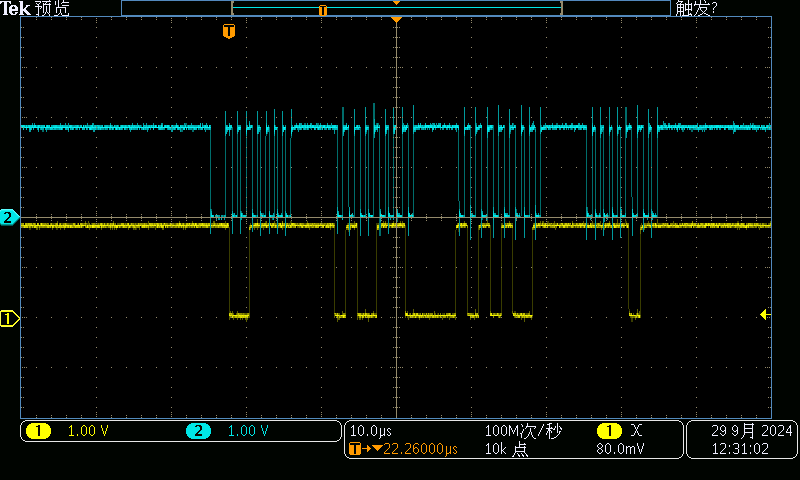
编译及运行App, 使用示波器抓sck & mosi管脚波形, 如下:
22.8 总结
spi-gpio.c 驱动通过 bit-banging 模拟了一个 SPI 控制器,允许在没有硬件 SPI 控制器的系统上使用 GPIO 引脚进行 SPI 通信。它的注册流程包括初始化 spi_master 结构、配置 GPIO 引脚、设置传输函数,并最终注册到 SPI 核心层。应用程序通过标准的 /dev/spidev 接口与 SPI 设备通信。bit-banging 方法虽然效率不如硬件 SPI 控制器,但为灵活使用 GPIO 提供了便利的解决方案。